


CDL Vertical Multistage Pumps: Stainless Steel Construction, Applications, and Selection Tips
Views: 0 Author: Site Editor Publish Time: 2026-08-09 Origin: Site


Industrial fluid transfer systems demand uncompromising reliability to maintain daily operations. Plant managers constantly battle to secure robust fluid delivery networks. Unexpected downtime disrupts production schedules and drastically affects bottom-line profitability. Mechanical seal failures act as hidden drains on corporate budgets. Energy inefficiencies waste massive amounts of electrical power every year.
Facility layouts frequently present strict spatial limitations for new equipment. Standard horizontal configurations require massive concrete pads and excessive floor space. You need equipment engineered for high head pressure in a compact vertical footprint. We introduce CDL vertical multistage pumps as the standard solution for these demanding environments.
This comprehensive guide will equip you to evaluate, size, and implement CDL and CDLF series units. You will discover an evidence-based framework for selecting the exact pump your system requires. We will explore hydraulic sizing, metallurgy choices, and mechanical seal configurations thoroughly.
Key Takeaways
Material Distinction: CDL (cast iron base/head) and CDLF (all-wetted stainless steel) serve different operational environments and budget constraints.
High-Pressure Reliability: Engineered primarily for continuous-duty applications like reverse osmosis water treatment, boiler feeding, and HVAC pressure boosting.
Sizing Imperatives: Accurate selection requires rigorous calculation of System Head, Flow Rate, and Net Positive Suction Head (NPSH) to prevent cavitation.
Lifecycle Focus: Proper alignment, initial venting, and VFD (Variable Frequency Drive) integration significantly reduce mechanical wear.
The Engineering Core of CDL Vertical Multistage Pumps
The inline vertical multistage pump architecture relies on a highly efficient spatial design. The suction port and discharge port align on the exact same horizontal axis. This straight-line configuration fits perfectly into cramped mechanical rooms. You do not need to pour massive horizontal concrete foundations. The vertical orientation utilizes empty vertical space instead of valuable floor real estate.
Engineers achieve massive head pressure by stacking multiple impellers inside the pressure casing. We refer to these individual impellers as stages. The pumping process follows a precise mechanical sequence:
Fluid enters the inline suction port at the pump base.
The first impeller accelerates the liquid centrifugally to build initial velocity.
Internal diffusers smoothly redirect the fluid upward to the next impeller stage.
Pressure multiplies incrementally as the fluid passes through each successive impeller.
The highly pressurized liquid exits through the inline discharge port.
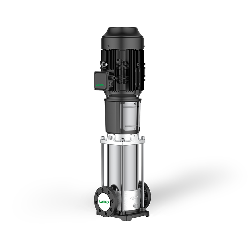
Let us detail the standard construction features of these robust units. You will find a standard TEFC (Totally Enclosed Fan Cooled) motor mounted at the top. This motor enclosure prevents destructive dust and moisture from reaching the electrical windings. The pump connects to the motor via a rigid split coupling. The system utilizes sophisticated cartridge mechanical seals to prevent dangerous fluid leaks.
Hydraulic efficiency truly sets these modern units apart from older technologies. Premium stainless steel vertical multistage pumps utilize precision-stamped internal components. The stamping process creates incredibly smooth metal surfaces on the impellers and diffusers. This surface smoothness minimizes internal fluid friction losses dramatically. Traditional cast sand models suffer from rougher interior passages. Fluid turbulence wastes valuable energy in those older designs. Precision stamping ensures your operation saves electricity during continuous pumping cycles.
CDL vs. CDLF: Material Selection and Cost-to-Benefit Analysis
Material selection strictly dictates your pump's operational longevity. We must choose between the standard CDL and the premium CDLF series carefully. The standard CDL series offers a highly practical hybrid construction approach. It utilizes strong stainless steel impellers internally to maintain hydraulic efficiency. However, it features cast iron suction bases, discharge bases, and motor stools.
Cast iron provides excellent structural stability and absorbs operational vibrations well. We highly recommend standard CDL models for non-corrosive environments. They excel at transferring clean municipal water reliably. They also handle mild industrial cooling water without degradation. This hybrid approach keeps your initial purchasing costs relatively low.
The CDLF series delivers a completely full stainless steel solution. Every single wetted component consists of AISI 304 or AISI 316 stainless steel. This includes the outer sleeve, impellers, diffusers, and the entire base assembly. This premium metallurgy resists chemical attacks highly effectively. You gain maximum protection against internal rust and structural degradation.
How do you evaluate this critical purchasing decision? You must frame your choice entirely around fluid composition. Pumping demineralized water attacks standard cast iron aggressively. The water leaches iron particles from the baseplate over time. This leaching ruins your water purity instantly. Paying the premium for a CDLF unit makes mathematical sense here.
Mildly corrosive fluids will destroy a standard cast iron pump within months. The full stainless CDLF build prevents this premature equipment failure entirely. Strict hygiene compliance often mandates CDLF models as well. Food processing facilities and pharmaceutical plants require them by law. The initial extra investment in stainless steel prevents catastrophic system downtime later.
Core Industrial Applications and Success Criteria
These robust pumps handle extremely demanding tasks across multiple industrial sectors. We consistently see them deployed in areas requiring high continuous pressure. Industrial reverse osmosis water treatment systems rely heavily on these vertical units. RO membranes require exceptionally high osmotic pressure to push water through microscopic pores. The system must overcome this immense resistance continuously.
A precision vertical multistage pump delivers the necessary smooth and relentless force. It eliminates damaging pulsating flow patterns completely. Smooth fluid delivery protects the delicate and expensive RO membranes from structural tearing. Consistent pressure ensures optimal clean water recovery rates.
Boiler feed and condensate recovery systems present another major application category. Industrial boilers demand continuous high-head water delivery to maintain steam production. The feedwater often reaches safely elevated temperatures. Advanced high-pressure vertical multistage pumps handle these extreme thermal stresses perfectly. They push water into highly pressurized boiler vessels without faltering. The inline design easily handles the thermal expansion associated with hot condensate.
Municipal and commercial pressure boosting systems also utilize them extensively. High-rise buildings need reliable upward water supply to reach penthouse levels. HVAC circulation networks require steady fluid movement across sprawling campuses. Success in these commercial spaces demands strict acoustic performance. You need very low noise emissions in occupied residential buildings. Excellent energy efficiency serves as another critical success criterion. The vertical multi-impeller design meets both of these commercial demands effortlessly.
Sizing and Selection Criteria for High-Pressure Vertical Multistage Pumps
Proper hydraulic sizing guarantees your long-term operational success. We must map the exact Flow (Q) and Head (H) requirements accurately. You start by reading the manufacturer's specific pump performance curve. This graph plots fluid flow rates against pressure generation capabilities. Engineers should select a pump very carefully based on this curve.
Your system's calculated operating point must fall near the pump's Best Efficiency Point (BEP). Operating near the BEP minimizes damaging shaft vibration. It also prevents excessive energy waste. Operating too far to the right of the curve overloads the motor. Operating too far to the left causes severe internal recirculation issues.
Next, we must aggressively address Net Positive Suction Head (NPSH). Cavitation destroys stainless steel impellers rapidly. Cavitation occurs when liquid pressure drops below its vapor pressure. Tiny vapor bubbles form and collapse violently against the metal. This sounds like pumping a bag of glass marbles.
You must calculate the available NPSH (NPSHa) in your unique piping system. Then, compare it against the pump's required NPSH (NPSHr). Your system's NPSHa must always exceed the pump's NPSHr by a safe margin. This fundamental engineering rule prevents destructive vapor bubbles from ever forming.
Seal and elastomer selection also requires your strict attention. You must match the mechanical seal materials to your specific fluid. Consider the exact liquid temperature and chemical makeup carefully. Using the wrong rubber elastomer causes immediate seal leakage.
Table: Mechanical Seal Elastomer Comparison
Elastomer Type | Primary Industrial Application | Maximum Temperature Limit | Chemical Resistance Profile |
|---|---|---|---|
EPDM (Ethylene Propylene) | Clean water, hot water, mild alkalis | Up to 120°C | Excellent for water; Poor against oils |
FKM (Viton) | Oils, fuels, mild chemicals | Up to 90°C | Excellent against oils; Poor for hot steam |
NBR (Nitrile) | Cold water, standard HVAC | Up to 80°C | Good general purpose; Fails in extreme heat |
Implementation Realities, Maintenance, and Risk Mitigation
Installation errors cause many premature pump failures in the field. We must address these common rollout risks directly to protect your equipment. Improper pipe strain ranks as a top mechanical failure cause. Piping must never rely on the pump casing for physical support. You must support all connecting pipes independently using proper hangers. When piping rests on the pump, it distorts the casing and misaligns the internal shaft.
Baseplate leveling errors also create massive mechanical issues. An uneven concrete base causes destructive shaft misalignment over time. You must grout the baseplate perfectly flat. Use precision laser alignment tools before tightening the final anchor bolts.
Variable Frequency Drive (VFD) integration offers massive operational benefits. VFDs adjust the pump's motor speed based on real-time system demand. They utilize PID loops to maintain a constant pressure regardless of flow changes. This control method saves enormous amounts of electrical power during low-demand periods. It also provides a soft-start function, which eliminates damaging water hammer effects.
However, VFDs introduce specific electrical risks. They can cause harmful high-frequency bearing currents inside the motor. These currents arc across the bearings and destroy the smooth metal races. You should install shaft grounding rings to mitigate this electrical damage effectively. Upgrading to VFD-rated motor bearings also prevents this high-frequency destruction.
Lifecycle maintenance becomes much easier with modern vertical units. These pumps feature advanced cartridge-style mechanical seals. Cartridge seals allow for rapid and error-free replacement during maintenance windows. You do not need to remove the heavy motor to access the seal. You simply detach the split coupling and pull the cartridge out. This design significantly reduces your maintenance downtime. Technicians can swap the entire seal assembly safely in under thirty minutes.
Conclusion
Choosing the correct CDL or CDLF pump requires careful engineering thought. You must balance pump metallurgy against your specific fluid composition. Precise hydraulic sizing ensures your system operates smoothly at peak efficiency. Application matching prevents unexpected mechanical failures and keeps your production schedules intact. Proper installation procedures protect the internal bearings from premature wear.
Take direct action to secure your next fluid transfer upgrade. First, compile all your crucial fluid data carefully. Document the maximum liquid temperature, exact chemical composition, and daily flow requirements. Next, calculate your exact system head demands including all pipe friction losses. Finally, consult a qualified pump engineer to review your technical findings. They will help you finalize the optimal performance curve and precise motor specifications.
FAQ
Q: What is the maximum fluid temperature a standard CDL/CDLF pump can handle?
A: Standard CDL and CDLF models typically handle fluid temperatures up to 70°C safely. If your process involves hotter liquids, you need specialized hot water variants. These upgraded versions utilize specific high-temperature seals to manage fluids up to 120°C. Your exact thermal limit ultimately depends on the specific mechanical seal elastomer configuration chosen.
Q: Can a vertical multistage pump run dry?
A: No, these pumps must never run dry under any circumstances. The internal mechanical seals rely entirely on the pumped fluid for essential cooling and lubrication. Dry running causes severe frictional heat and immediate seal face destruction. We strongly recommend installing dry-run protection sensors to shut the motor down immediately if fluid stops flowing.
Q: How do I choose between AISI 304 and AISI 316 stainless steel for my application?
A: You should base this choice entirely on the fluid's chloride concentration. AISI 304 stainless steel serves perfectly for standard clean water and mildly aggressive fluids. If you pump highly corrosive liquids or water with elevated chloride levels, upgrade to AISI 316. It contains molybdenum, which offers superior resistance against pitting and chemical attacks.
Q: Are CDL pumps self-priming?
A: These are non-self-priming centrifugal pumps. They cannot draw fluid up from a lower level through an empty pipe on their own. You must provide a flooded suction environment. Alternatively, you can install a reliable foot valve on the suction line. You must vent the pump casing thoroughly to remove all trapped air before every initial startup.


