


Submersible Sewage Pumps: Setting Minimum Levels and Float Stops
Views: 0 Author: Site Editor Publish Time: 2026-10-26 Origin: Site


Proper fluid level management forms the backbone of any reliable wastewater system. A single miscalibrated switch can turn a robust machine into a failing liability overnight. Without accurate level controls, you risk catastrophic facility downtime. Fluid dynamics and motor cooling requirements demand precise calibration to keep systems running smoothly.
The greatest operational risk comes from incorrect "Off" settings. Setting the stop point too low causes catastrophic dry running. Conversely, setting it too close to the start point triggers excessive cycling. Both scenarios rapidly destroy motor windings and mechanical seals. Facility managers often overlook these parameters until a premature failure occurs.
This guide explores how to balance system efficiency with mechanical protection. We will examine float architecture, cycle mechanics, and precision tuning protocols. You will learn exactly how to configure your level controls for maximum equipment longevity. Proper implementation ensures a resilient pumping station ready to handle peak demands.
Key Takeaways
Optimal Cycling: Why short-cycling is the primary cause of premature motor failure in sewage systems.
The "Minimum Level" Logic: Understanding NPSH (Net Positive Suction Head) requirements and motor cooling zones.
Float Architecture: Differentiating between tethered floats, weighted switches, and vertical sensors.
Precision Tuning: Step-by-step logic for setting stop-points to prevent cavitation and ensure proper priming.
Understanding the Mechanics of Pump Cycling
Basin volume directly impacts your pump duty cycle. Pit size dictates the allowable gap between start and stop levels. A small basin requires a narrow operating band. This narrow band forces the equipment to activate frequently to manage incoming flow. Conversely, a larger basin accommodates wider level swings. Wider swings extend the resting period between activation cycles. You must match your start and stop configurations to the specific geometry of your wet well.
Modern sewage pumps require adequate fluid coverage to dissipate internal heat. The surrounding wastewater acts as a massive heat sink. When fluid levels drop below the motor housing, the equipment loses its primary cooling mechanism. Continuous operation in this exposed state leads to rapid thermal overload. Stator insulation degrades quickly under extreme heat. Over time, inadequate cooling guarantees catastrophic motor failure.
Short-cycling represents one of the most destructive forces in wastewater management. Every time a motor starts, it draws a massive inrush current. This current spike generates intense heat within the windings. If the resting period is too brief, the motor cannot shed this accumulated heat. Short-cycling also wreaks havoc on mechanical components. Start switches and capacitors degrade rapidly under high-frequency activation. Industry standards typically recommend keeping motor starts below ten per hour. Exceeding manufacturer specifications voids warranties and guarantees premature breakdowns.
Determining Minimum Operational Levels
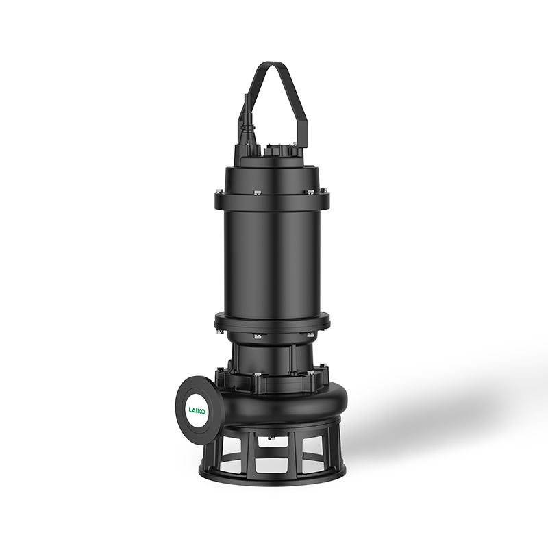
You must always prioritize the manufacturer specifications when configuring a submersible sewage pump. The equipment nameplate and the Installation, Operation, and Maintenance (IOM) manual provide critical baseline data. These documents outline the absolute minimum submergence required for safe operation. Ignoring these guidelines invites immediate mechanical trouble. Engineers design these units to operate within strict thermal and hydraulic parameters. Your level settings must respect these engineered boundaries.
Net Positive Suction Head (NPSH) requirements dictate how low you can safely draw down the fluid. The suction inlet must remain deeply submerged to prevent air ingestion. When fluid levels drop too low, the pressure at the impeller eye plummets. This pressure drop causes wastewater to vaporize, creating tiny bubbles. These bubbles violently implode against the impeller vanes. We call this destructive process cavitation. Cavitation causes severe internal erosion, destroying impellers and volutes in a matter of months.
Basin turbulence management plays a crucial role in setting the stop point. As fluid levels decrease, the velocity of the water entering the pump increases. If the stop point is too low, this high-velocity flow creates surface vortices. A vortex acts like a tornado, pulling surface air directly into the suction inlet. Trapped air and sewer gases accumulate inside the volute. This phenomenon causes the equipment to lose its prime, leading to dangerous dry-running conditions.
Follow these steps to determine your minimum operational levels safely:
Consult the IOM manual to identify the minimum continuous submergence line.
Measure the distance from the basin floor to the top of the motor housing.
Calculate the required NPSH margin based on your specific flow rate and elevation.
Add a safety buffer of at least six inches above the highest calculated minimum level.
Best Practices for Level Determination
Always measure levels from the true bottom of the basin, accounting for sludge buildup.
Factor in the maximum anticipated inflow rate during heavy storm events.
Verify your calculations against Hydraulic Institute (HI) standards for pump intake design.
Configuring Float Stops for Reliable Performance
The tethered float method remains a staple in wastewater level control. You adjust the pivot point to control the "on" and "off" swing. A longer tether creates a wider operating band, reducing cycle frequency. A shorter tether tightens the band, which is critical for narrow-basin applications. However, setting the tether too short restricts buoyancy. The float may fail to tip far enough to engage the internal microswitch. You must find the perfect balance between cycle time and mechanical reliability.
Engineers frequently debate the merits of fixed versus adjustable switches. Tethered floats offer rugged mechanical reliability. They handle heavy solids and turbulent environments exceptionally well. Vertical float switches provide superior precision. They slide up and down a fixed rod, activating at exact elevations. Vertical switches excel in confined spaces where tethered floats might snag. However, vertical mechanisms are more susceptible to jamming from grease and debris.
Table 1: Float Switch Configuration Comparison
Switch Type | Primary Advantage | Ideal Application | Common Vulnerability |
|---|---|---|---|
Tethered Float | High durability and debris resistance | Large basins with heavy solids | Requires wide clearance radius |
Vertical Float | Pinpoint activation accuracy | Narrow pits and confined spaces | Prone to grease jamming |
Weighted Switch | Easy depth adjustment from surface | Deep municipal lift stations | Cable entanglement risks |
Setting the exact "Stop" point requires strategic thinking. Ideally, the stop point should sit above the motor housing. This elevation ensures continuous thermal protection. However, the stop point must remain below the secondary intake level. If wastewater backs up into the inlet pipes, solids settle out prematurely. This settling causes severe pipe blockages. Your stop point must balance motor cooling with proper basin drainage.
Redundancy protocols protect your facility from catastrophic overflows. Never rely on a single float to manage your entire system. Best practices dictate integrating high-level alarms independent of the primary control float. If the main switch fails, the alarm float triggers a secondary circuit. This circuit alerts facility managers and can activate a backup unit. Redundancy transforms a potential disaster into a manageable maintenance task.
Implementation Realities and Common Pitfalls
Solid buildup poses a massive threat to float mechanisms. Setting levels too low encourages grease and solid accumulation. Fats, oils, and grease (FOG) float on the surface of the wastewater. If the basin drains too far, this grease layer coats the floats and cables. Over time, the grease hardens into a heavy crust. This crust alters the buoyancy of the float, preventing it from tipping. The system either fails to start or refuses to shut off.
Obstruction hazards routinely compromise level control systems. You must ensure the float range-of-motion remains completely clear. Floats easily snag on basin walls, power cables, and discharge piping. A snagged float sends false signals to the control panel. Secure all loose cables using heavy-duty zip ties or dedicated cable brackets. Position the floats in a clear zone, away from the turbulent inflow pipe.
Calibration verification separates professional installations from amateur setups. You must dry-test the float sequence before final system commissioning. Manually lift each float to verify panel response. Confirm the start, stop, and alarm sequences trigger at the correct elevations. Skipping this step often leads to immediate operational failures once the basin fills. Dry-testing takes minutes but saves hours of troubleshooting later.
Environmental factors heavily influence float performance. Liquid temperature and chemical density shift the buoyancy of standard floats. Industrial wastewater often contains heavy chemicals or high-temperature discharge. Hot water reduces fluid density, causing standard floats to ride lower in the basin. You may need to specify high-temperature or chemical-resistant floats for specialized applications. Always match your float materials to the specific characteristics of your effluent.
Common Mistakes to Avoid
Tying float cables directly to the discharge pipe without proper standoff brackets.
Ignoring the manufacturer's recommended minimum tether length.
Placing the "Off" float directly under the incoming effluent stream.
Failing to account for the displacement volume of the equipment itself.
Strategic Selection: Upgrading Your Float Control System
Standard mechanical floats work well for basic applications. However, complex facilities eventually outgrow these simple devices. Transitioning to ultrasonic sensors or pressure transducers offers massive operational advantages. Ultrasonic sensors bounce sound waves off the fluid surface to measure depth. Pressure transducers sit at the bottom of the pit, calculating depth based on hydrostatic pressure. Both technologies eliminate moving parts entirely. They provide continuous, real-time level data to your control panel.
Scalability considerations should drive your level control strategy. As your facility grows, you may need to integrate redundant lead/lag pumping systems. A lead/lag setup alternates duties between two units, ensuring even wear. Advanced sensors make lead/lag integration seamless. You can program exact activation points via a digital interface. If inflow exceeds the capacity of the lead unit, the system automatically triggers the lag unit. Mechanical floats struggle to provide this level of dynamic scalability.
Investing in precise level controls yields a massive maintenance return on investment. Accurate sensors drastically reduce long-term labor costs. Maintenance teams spend fewer hours performing manual resets or untangling fouled cables. Furthermore, precise controls eliminate the short-cycling and dry-running events that destroy motors. By protecting the mechanical integrity of your equipment, you extend its operational lifespan by years. Upgrading your controls transforms reactive troubleshooting into proactive system management.
Conclusion
Precision in float setting represents a direct investment in motor life and facility uptime. Accurate level controls prevent the destructive forces of cavitation, thermal overload, and short-cycling. By respecting minimum submergence requirements, you protect your infrastructure from premature mechanical failure. Upgrading to advanced sensor technologies further insulates your facility against unexpected downtime.
Before commissioning any system, conduct a comprehensive audit. Verify your settings against manufacturer head/flow charts and specific basin geometry. Dry-test all sequences and confirm your redundancy protocols are active. Take action today to inspect your wet wells, clear grease from your tethers, and recalibrate your stop points.
If you encounter complex basin geometries or aggressive industrial effluent, do not guess your settings. We invite you to consult with engineering support for specific application design. Expert guidance ensures your control system integration matches your exact hydraulic requirements.
FAQ
Q: How much water should remain in the pit after the pump stops?
A: Sufficient to cover the volute intake without encouraging rapid sediment build-up.
Q: Can I adjust the float switch myself?
A: Yes, provided the power is disconnected and the tether length is adjusted within the manufacturer-recommended range.
Q: Why does my pump turn on and off every few seconds?
A: Likely an incorrect float stop setting or a failed check valve causing backflow.
Q: What is the best way to prevent grease from sticking to my float?
A: Proper installation alignment and periodic flushing/cleaning cycles.
Q: Do I need a separate control panel for my float switches?
A: For commercial-grade sewage pumps, a dedicated control panel is highly recommended for enhanced protection and alarm monitoring.


