


What Is a Booster Pump and When Do You Need One?
Views: 0 Author: Site Editor Publish Time: 2026-09-02 Origin: Site


Low water pressure acts as a severe operational bottleneck rather than a mere nuisance. It damages equipment efficiency and limits functionality across residential buildings and sprawling commercial facilities. You cannot afford sluggish water delivery in high-stakes environments. Poor pressure disrupts manufacturing processes, extends cleaning times, and severely frustrates building occupants.
Simply adding a pump might seem like an immediate, foolproof fix. However, many facility managers and homeowners rush into purchases without proper evaluation. Misdiagnosing the root cause or selecting an incompatible pump architecture frequently leads to wasted capital, excessive operational noise, or premature system failure. You must understand your existing infrastructure before buying new hardware. Slapping a powerful motor onto a degraded pipe network will only cause more damage.
This guide provides an objective, step-by-step framework for determining if a pressure-enhancing solution is truly necessary. We will help you diagnose your plumbing issues accurately. Furthermore, we will explore how to evaluate and select the right system to perfectly meet your specific daily operational demands.
Key Takeaways
Core Function: Booster pumps do not create water; they amplify existing pressure and flow to overcome gravity, distance, and pipe friction.
Diagnosis First: Verify that pressure loss isn't caused by clogged pipes, closed valves, or municipal supply leaks before investing in a pump.
System Selection: Choosing between single-stage, multistage, or inverter-driven systems depends entirely on peak demand, footprint constraints, and energy efficiency goals.
Implementation Risk: Failing to account for backflow prevention, dry-run protection, and municipal regulations are the most common points of failure in new installations.
1. What Is a Booster Pump? (Mechanics & System Role)
To make informed system upgrades, you must first understand the fundamental mechanics of the equipment. A booster pump operates as a highly specialized intermediary machine. Briefly defined, a booster pump is an intermediary centrifugal machine that increases fluid pressure within an existing closed-loop or delivery system. It acts as an accelerator. It takes water entering at a low velocity and forces it out at a significantly higher pressure.
Many people confuse these machines with primary extraction pumps. Standard pumps actively draw water directly from a natural source. For example, a submersible pump pushes water out of a deep underground well, or a jet pump pulls water from a surface reservoir. Conversely, a booster pump requires an incoming baseline pressure to function effectively. It cannot pull water out of thin air or a dry pipe. It strictly receives water from a municipal line or a storage tank and amplifies the existing momentum.
The anatomy of these systems relies on a few critical components working in unison. You will typically find an electric motor, one or more impellers, a volute casing, an inlet, an outlet, and a pressure sensing switch. The motor drives a shaft connected to the impellers. As water enters the inlet, the spinning impellers use centrifugal force to fling the water outward. This rapid motion dramatically increases the fluid's velocity. The casing then guides this high-velocity water toward the outlet, converting the speed into usable pressure. The pressure switch serves as the brain, turning the motor on or off based on preset pressure thresholds.
2. Measurable Signs You Need a Pressure Booster (Problem Framing)
Deciding to upgrade your plumbing infrastructure requires hard data. You cannot rely on subjective feelings about showerhead flow. You must quantify the deficit using industry-standard measurements. For residential and light commercial settings, standard acceptable water pressure ranges from 40 to 60 PSI (Pounds per Square Inch). Anything below 40 PSI typically causes noticeable performance drops. You can easily test your baseline pressure by attaching a localized pressure gauge to a standard hose bib or utility sink. Turn off all other water sources, open the valve, and read the static pressure.
Often, a system shows adequate pressure at rest but fails during peak operational hours. We call these peak demand pressure drops. Imagine a commercial facility where the static pressure reads a healthy 50 PSI. However, when multiple fixtures, industrial nodes, or wash-down stations operate simultaneously, the dynamic pressure plummets to 20 PSI. The existing supply lines simply cannot deliver the required volume fast enough. In these scenarios, a supplementary system becomes vital to maintain steady flow under heavy loads.
The origin of your water heavily influences pressure behavior. Municipal supplies and private wells face distinctly different limitations. Municipal pressure drops frequently result from geographical distance from the main processing facility. Alternatively, significant elevation changes weaken city flow. Water loses roughly 1 PSI for every 2.31 feet of vertical climb. Well water systems experience fluctuations tied to the well pump's cycling phases. A low-yielding well often requires an intermediary atmospheric storage tank paired with a dedicated booster setup to ensure consistent delivery to the building.
Before spending money, you must identify false flags. A booster pump represents the wrong investment if underlying mechanical failures cause your low pressure. Scaling or mineral buildup inside old galvanized pipes restricts flow heavily. A failing pressure-reducing valve (PRV) can artificially choke off your water supply. Likewise, undetected underground leaks bleed pressure away before it reaches your facility. You must rule out these issues first.
Diagnostic Chart: Pump Necessity vs. System Repair
Observed Symptom | Potential Underlying Cause | Recommended Action |
|---|---|---|
Low pressure localized to only one single faucet or showerhead. | Clogged aerator or heavily calcified fixture cartridge. | Remove, soak in vinegar, and clean or replace the aerator. |
Gradual facility-wide pressure loss over several months or years. | Severe pipe scaling, corrosion, or hidden underground supply leaks. | Hire a plumber to inspect piping integrity and perform leak detection. |
Pressure drops severely only when multiple fixtures run simultaneously. | Supply line diameter is insufficient for the building's peak demand volume. | Size and install an appropriate pressure amplification system. |
Static gauge reading directly at the municipal entry point is below 35 PSI. | City utility infrastructure limitations or high geographical elevation. | Install an approved amplification system with a backflow preventer. |
3. Evaluating Pump Architectures: Which Type Fits Your Application?
Once you verify the need for mechanical amplification, you must select the correct architecture. Not all systems are built equally. Choosing the wrong design leads to inefficiency and excessive wear.
Standard single-stage pumps represent the simplest architecture. They utilize one single impeller spinning inside the casing. These units work best for minor, single-point residential applications. If you only need to boost pressure for an irrigation sprinkler zone or a single remote bathroom, a single-stage unit provides a cost-effective solution. However, they lack the capacity to handle heavy commercial loads.
When demand increases, facilities turn to multistage designs. A horizontal multistage centrifugal pump features multiple impellers aligned on a horizontal shaft. Water passes from one impeller to the next, gaining pressure at each stage. This architecture works best for applications requiring steady, moderate-to-high pressure. You frequently see them in environments with vertical space constraints, like cramped mechanical basements. The primary advantage lies in easier maintenance access. Technicians can often inspect the motor without completely dismantling the overhead plumbing. The main downside is the larger floor footprint required to accommodate the horizontal motor layout.
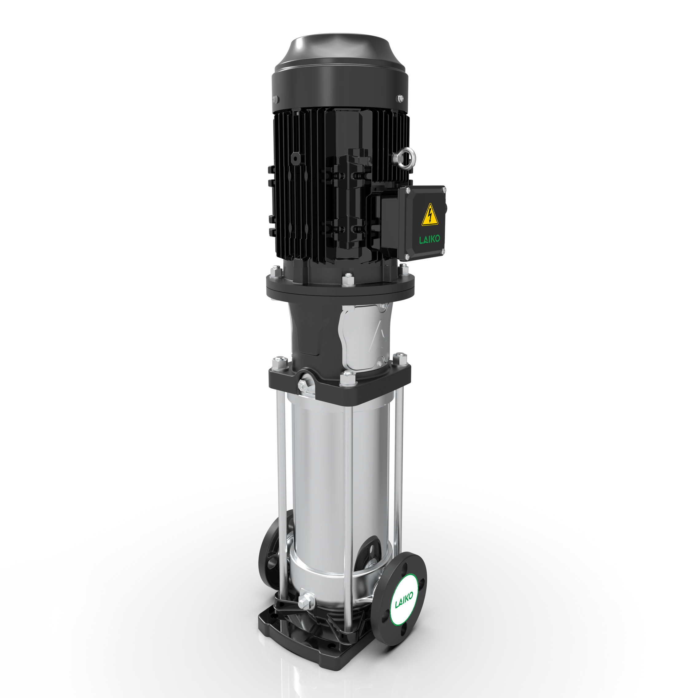
For towering structures or heavy industry, orientation matters. A vertical multistage centrifugal pump aligns its shaft and impellers upright. This design is best for high-pressure industrial processes, commercial complexes, or high-rise applications requiring substantial head pressure to push water up dozens of floors. These units are highly efficient. They boast an excellent footprint-to-power ratio, allowing you to install powerful machinery in tight corners. However, they require sufficient vertical overhead clearance for installation and maintenance. Furthermore, the vertical shaft demands highly precise alignment to prevent premature bearing failure.
Modern efficiency standards have pushed technology further. A constant-pressure inverter water supply system represents the pinnacle of fluid management. This architecture is best for facilities with highly fluctuating water demands. Hotels, manufacturing plants, and large estates face drastically different water needs between 3:00 AM and 8:00 AM. The mechanism uses Variable Frequency Drives (VFD) connected to pressure sensors. The drive adjusts the motor speed in real-time based on actual demand. If one person opens a tap, the motor spins slowly. If twenty showers open, it ramps up immediately. From a return-on-investment lens, these systems demand higher upfront capital expenditure. However, they yield significant long-term savings on energy consumption. They also drastically reduce mechanical wear by ensuring smooth motor starts and eliminating destructive water hammer effects within the pipes.
4. Key Evaluation Criteria for Shortlisting (System Sizing & Specs)
Selecting an architecture is only half the battle. You must perfectly size the equipment to match your building's unique hydraulic profile. Guessing these numbers leads to catastrophic system failures.
First, you must understand the critical relationship between Flow Rate (GPM) and Total Dynamic Head (TDH). Flow rate, measured in Gallons Per Minute, dictates how much volume you need. Total Dynamic Head represents the total resistance the system must overcome, including gravity, vertical lift, and internal pipe friction. These two metrics share an inverse relationship. As flow increases, the maximum deliverable pressure decreases. Buyers must accurately map their required GPM against the manufacturer's specific pump curve. You want your normal operating demand to fall directly in the middle, or the "Best Efficiency Point," of that curve.
Power supply and motor sizing cannot be ignored. You must match the horsepower (HP) and electrical phases to your existing infrastructure. Residential homes generally support 115V or 230V single-phase power. Industrial sites often utilize 460V three-phase power, which runs motors much more efficiently. Installing a three-phase motor in a building wired only for single-phase power forces you into expensive electrical retrofits. Always verify your breaker panel capacity before purchasing.
Material construction dictates the lifespan and safety of your system. We strongly highlight the importance of stainless steel impellers and housings. If the system handles drinking water, the materials must meet strict potable water compliance standards (such as NSF/ANSI 61). Stainless steel provides superior corrosion resistance and longevity compared to cheaper cast iron or plastic alternatives. Cast iron rusts over time, releasing particulates into the water stream. Plastic components can warp under continuous heat or high-pressure stress.
Finally, consider the acoustic profile of the machinery. Pumping water is a violent, mechanical process. High-RPM multistage systems generate significant noise. You must factor in decibel (dB) ratings if the equipment will be installed near occupied spaces, residential bedrooms, or quiet office areas. An inadequately shielded unit sounds like a jet engine running in the next room.
4 Steps to Size Your System Properly
Audit Fixture Count: Count every sink, toilet, shower, and heavy appliance. Calculate the absolute peak simultaneous GPM requirement.
Calculate Total Lift: Measure the exact vertical distance from the pump installation site to the highest plumbing fixture in the building.
Account for Friction: Add an extra 10-15% to your head pressure calculations to account for friction loss through elbows, valves, and long pipe runs.
Read the Curve: Consult the manufacturer's performance curve chart. Ensure your GPM and TDH intersection point lands securely within the optimal operating range.
5. Implementation Realities: Compliance, Risks, and Installation
Procuring the right hardware guarantees nothing if the installation process is flawed. Integrating powerful mechanical equipment into existing plumbing introduces significant physical risks and strict legal liabilities. You must prioritize safety and compliance.
Regulatory compliance remains the most critical hurdle. Pushing pressurized water creates a risk of cross-connection contamination. If street pressure drops, your building's water could potentially flow backward into the public main. We strongly emphasize the absolute necessity of installing backflow preventers. These specialized valves protect municipal or source water from contamination. Always check local municipal codes and secure the necessary permits before cutting into the main line. Many jurisdictions mandate annual inspections for these prevention devices.
Mechanical threats like cavitation and dry running destroy equipment rapidly. Cavitation occurs when incoming pressure drops so low that the water effectively boils, forming vapor bubbles. When these bubbles hit the high-pressure side of the impeller, they collapse violently. This micro-explosion pits and destroys stainless steel over time. Dry running happens when a pump operates without sufficient incoming water. The water inside a casing acts as a crucial coolant and lubricant. Without it, mechanical seals melt within minutes. Therefore, installing low-pressure cut-off switches is entirely non-negotiable for system longevity. These sensors kill the motor instantly if incoming flow stops.
Thermal expansion presents another hidden danger. When you introduce a backflow preventer, you create a "closed-loop" plumbing system. Water expands as heaters warm it. Without a way to push backward into the city main, this expanding water causes pressure spikes that rupture pipes. We discuss the necessity of pairing the booster setup with a properly sized thermal expansion tank. This tank contains a pressurized air bladder that compresses to absorb expanding water volume. It also acts as a buffer to prevent rapid motor cycling.
Finally, address vibration and piping stress. A heavy motor spinning at 3450 RPM generates continuous micro-vibrations. If you bolt the unit directly to rigid copper or PVC pipes, those vibrations will eventually crack the joints. We highly recommend using thick neoprene vibration isolation pads under the mounting base. Furthermore, utilize flexible, braided stainless steel pipe connectors between the building's rigid pipes and the system's inlet and outlet ports. These flexible joints absorb the kinetic shaking, preventing catastrophic structural damage over time.
Conclusion
Overcoming poor water pressure requires more than guesswork; it demands a strategic engineering approach. A booster pump is a serious, system-level investment, not a simple plug-and-play appliance. Misunderstanding your current infrastructure or buying an incorrectly sized unit will inevitably compound your plumbing problems and drain your maintenance budget.
Your next steps must be methodical. First, conduct a thorough pressure audit using a localized gauge to rule out false flags like clogged pipes or hidden leaks. Next, meticulously map your facility's peak GPM demand and vertical lift requirements. Finally, consult with a certified plumbing technician or mechanical engineer. Use their expertise to select the exact performance curve and determine whether a horizontal, vertical, or inverter-driven architecture best suits your physical constraints and operational goals.
FAQ
Q: Will a booster pump increase my water flow (GPM) or just the pressure (PSI)?
A: It primarily increases pressure (PSI), which directly influences flow (GPM). By adding mechanical force, the system overcomes pipe friction and gravity. This added push allows water to travel faster through the existing pipe diameter, effectively delivering a higher volume of water per minute to your fixtures.
Q: Can I install a booster pump directly to the city water line?
A: In most jurisdictions, direct connection is heavily restricted or illegal. Pumping directly from the main can siphon water away from neighbors or collapse city pipes. Codes usually require installing an atmospheric break tank or highly specific reduced-pressure zone (RPZ) backflow prevention valves to protect the municipal supply.
Q: How long do commercial booster pumps typically last?
A: A high-quality commercial system generally lasts between 10 to 15 years. Lifespan depends heavily on incoming water quality, routine maintenance, and whether the system uses VFD technology. Variable Frequency Drives significantly reduce mechanical wear and tear, often extending the operational life of the motor and impellers.
Q: Does a constant-pressure inverter system run all the time?
A: No, it does not. The Variable Frequency Drive (VFD) constantly monitors system pressure. When demand drops to zero, the drive significantly ramps down the motor speed. It will quickly enter a standby or "sleep mode" to save energy, instantly waking up the millisecond a tap is opened.


