


What Do DN and PN Mean on Water Pump Flanges?
Views: 0 Author: Site Editor Publish Time: 2026-11-20 Origin: Site


Incorrect flange dimensions or pressure ratings cause catastrophic system leaks. They also trigger mechanical stress and compliance failures in industrial piping. Engineers often face severe operational setbacks. This happens when new pump connections fail to align perfectly with existing facility infrastructure. A simple oversight in procurement can halt a multimillion-dollar installation.
We must rely on established European and international flange standards. Frameworks like EN 1092-1 and DIN dictate safe and accurate pump procurement. These rigorous frameworks ensure system components integrate smoothly. They prevent dangerous mechanical compromises on the job site. This guide breaks down Nominal Diameter (DN) and Nominal Pressure (PN). We will clarify their precise roles in heavy-duty system design.
We will explain exactly how these metrics directly impact pump specification and long-term fluid dynamics. Finally, you will receive a practical evaluation framework. It helps you match flange ratings to your exact system demands for safe operation.
Key Takeaways
DN (Diamètre Nominal) defines the internal diameter and physical mating size of the flange, ensuring seamless alignment with system piping without flow restriction.
PN (Pression Nominale) designates the maximum safe working pressure (in bar) the flange can handle at a standard reference temperature (typically 20°C).
High-pressure applications rely heavily on PN accuracy; a high-head vertical multistage pump often requires PN16, PN25, or PN40 flanges to prevent gasket blowout.
Selecting between pump configurations (e.g., vertical vs. horizontal) changes how DN/PN specifications interface with existing facility footprint and piping geometry.
The Engineering Behind DN and PN: Framing the Specification Problem
Let us thoroughly define the core parameters driving industrial flange specifications. DN (Nominal Diameter) acts as a standardized, dimensionless designation. It identifies the physical mating size of pipework and pump connections. For example, a DN50 designation roughly translates to a 50-millimeter internal pipe diameter. The exact millimeter measurement fluctuates slightly based on wall thickness.
Crucially, the DN value strictly dictates the bolt circle diameter. It also determines the exact number of bolt holes required for connection. You cannot alter these physical constraints on the job site. PN (Nominal Pressure) indicates the maximum design pressure in bar. We measure this at a standard reference temperature of 20°C. A PN16 designation means the flange safely handles 16 bar of internal pressure. It does this at room temperature without deforming.
You must also account for the critical concept of temperature derating. As fluid temperature rises in boiler feeds, the safe operating pressure drops significantly. A flange handling 20°C water at 16 bar might only contain 10 bar safely if the water reaches 140°C.
Failing to perfectly match DN and PN between equipment and piping introduces severe risks. Mismatched connections force contractors into costly workarounds during installation. They might resort to custom welding or field modifications. These actions immediately void manufacturer warranties. They also introduce serious workplace safety hazards due to blowout risks. Procurement success demands an absolute 1:1 match. Your pump discharge flanges must align perfectly to the receiving pipework. You cannot compromise on these metrics. Doing so jeopardizes the entire fluid handling system.
How Flange Ratings Dictate Solution Categories
Matching pressure ratings to specific application demands ensures continuous system stability. Standard municipal water transfer systems typically operate under lower stress. They might only require a baseline PN10 rating to function safely. Conversely, high-rise building boosting applications handle extreme operational stress. Industrial boiler feed systems also face similar extreme conditions. These demanding environments require a vertical multistage water supply pump equipped with PN25 or higher-rated flanges. These heavy-duty connections withstand massive head pressure. They handle intense hydraulic shock without risking structural failure.
You must also carefully match fluid flow velocity to your chosen DN sizes. Specifying an undersized DN creates an immediate bottleneck in your piping system. This artificial restriction causes excessive friction loss, destroying system efficiency. It also triggers damaging cavitation. Cavitation occurs when vapor bubbles implode against the pump impeller. Undersized flanges also create intense mechanical vibration. This vibration travels aggressively through the entire pipework network.
On the other hand, an oversized DN reduces fluid velocity too much. Slow-moving liquids allow suspended solids and debris to settle inside the pipes. This settling eventually leads to severe blockages. Oversized flanges also force engineers to install expensive concentric reducers. Reducers bridge the dimensional gap but add unnecessary material costs and potential leak points.
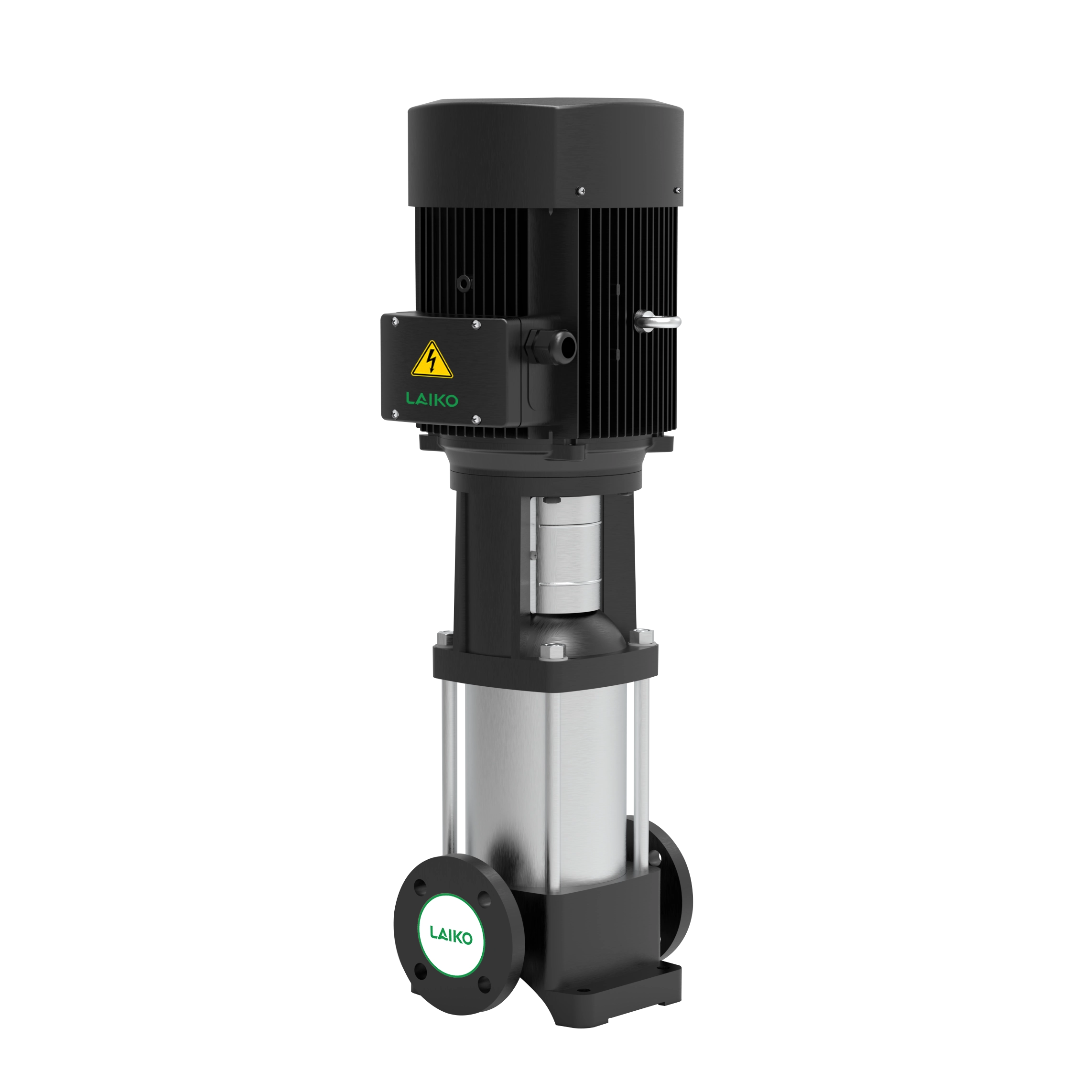
Configuration Impact: Evaluating Pump Architecture vs. Flange Layout
Pump architecture drastically influences how flange layouts integrate into your mechanical room. Inline flange systems offer distinct spatial and installation advantages for modern facilities. When you specify a Vertical multistage pump, you fundamentally simplify the piping design process. The suction and discharge flanges share the exact same DN and PN ratings. Furthermore, they sit perfectly on the same axis. This linear, straight-through arrangement makes installation in tight spaces highly efficient. Piping contractors do not need to design complex offsets or changes in pipe elevation.
Offset or orthogonal flange systems present a very different engineering challenge. Contrast the compact inline design with a standard horizontal end-suction centrifugal pump. These traditional units typically feature different DN sizes for their connections. The suction flange is usually larger to slow down incoming fluid and prevent cavitation. The discharge flange is smaller to maintain a pressurized, high-velocity output. This 90-degree geometry requires more complex piping transitions. It needs additional supports and consumes a much larger horizontal footprint on the factory floor.
Use the decision matrix below to guide your procurement strategy and select the right form factor for your facility.
Pump Configuration Decision Matrix
Configuration Type | Typical Flange Layout | Mechanical Footprint | Best Application Fit |
|---|---|---|---|
Inline (Same DN/PN on a single axis) | Minimal (Vertical orientation) | High-pressure, low-footprint systems | |
Horizontal End-Suction Pump | Orthogonal (Larger suction DN, smaller discharge DN) | Large (Horizontal orientation) | High-flow, lower-pressure baseline needs |
Implementation Risks: The Cost of Mismatched DN and PN
Ignoring flange compatibility guidelines leads to rapid mechanical degradation. It also causes severe safety incidents. Consider the extreme risk of bolting a PN10 pipe flange to a PN16 pump flange. The bolt holes might physically align during installation. However, the system remains heavily compromised. The overall pressure rating immediately defaults to the weakest link in the chain. Under sudden surge conditions or valve closures, the pressure spike easily exceeds 10 bar. You risk a catastrophic gasket blowout. A blowout sprays pressurized fluid across the entire mechanical room.
Standard clashes represent another major implementation trap for global procurement teams. European DIN/EN standards utilize DN and PN metrics. North American ANSI/ASME standards utilize NPS and Class ratings. Mixing these two distinct standards rarely works smoothly. We strongly warn against using forced adapter plates to marry these different systems. Adapter plates introduce secondary leak points. They increase the physical weight on the pump nozzle. Finally, they weaken the overall structural integrity of the piping connection.
Vibration and misalignment also destroy expensive fluid handling equipment. Mismatched flange faces cause immediate, severe operational issues. Do not bolt a raised face flange to a flat face flange. Doing so applies uneven torque across the connection when tightening the bolts. This incorrect DN bolting bends the hardware permanently. It transfers immense mechanical stress directly to the cast pump casing. The resulting vibration leads to premature bearing failure. It destroys the mechanical seal and ultimately requires a full pump replacement.
Shortlisting Logic: A Specification Checklist for Procurement
You need a rigorous, standardized checklist to prevent costly specification errors before issuing a purchase order. Follow these sequential steps to ensure perfect flange alignment.
Step 1: Audit Maximum System Pressure. Calculate your total static head plus all anticipated friction losses through valves and fittings. You must ensure the selected PN rating exceeds the pump's absolute shut-off head. Do not base your PN selection merely on the standard operating duty point. Systems frequently experience pressure spikes.
Step 2: Confirm Fluid Temperature Constraints. Always cross-reference your maximum fluid temperature with the specific flange material's PN derating curve. Materials behave differently under heat. A standard cast iron PN16 flange operates safely at 16 bar at 20°C. However, it may only handle 13 bar safely if the fluid temperature reaches 120°C.
Step 3: Verify Mating Geometries. Inspect the finer mechanical details of the connection. Ensure exact matching of DN sizes, PN ratings, and flange face types. Verify the bolt-hole count and bolt circle diameter match perfectly before signing off on the purchase order.
Best Practice: Always request certified technical dimension drawings from the pump manufacturer to confirm flange standards before finalizing your piping layout.
Common Mistake: Assuming all PN16 flanges have the exact same bolt hole patterns across different materials or updated standard revisions. Always verify the specific EN 1092-1 table.
Conclusion
DN and PN act as the mechanical and safety foundation of any fluid handling system, rather than just arbitrary dimensions on a spec sheet.
Flange alignment guarantees system longevity, whether you are evaluating a high-pressure vertical multistage pump or a high-volume horizontal unit.
Accurate specification prevents catastrophic gasket blowouts, uneven torque application, and premature bearing failures.
Review material derating curves meticulously to ensure your chosen PN rating holds up under high-temperature operational conditions.
Next Step Action: Encourage your facility engineers and procurement teams to consult detailed pump performance curves and official ISO/EN flange tables to finalize their technical shortlists.
FAQ
Q: Can I connect a PN16 flange to a PN10 flange?
A: Physically possible if the bolt circle matches, but strongly discouraged. The entire system's safe rating drops to PN10, creating compliance and safety risks.
Q: Does DN50 mean exactly 50mm internal diameter?
A: No, it is a nominal reference. The exact internal diameter varies slightly based on the pipe schedule/wall thickness.
Q: How do DN/PN standards compare to ANSI flange sizes?
A: DN corresponds to NPS (Nominal Pipe Size) in inches, while PN roughly aligns with ANSI Class ratings (e.g., PN20 is roughly Class 150), but they are not directly interchangeable without specialized adapters.


